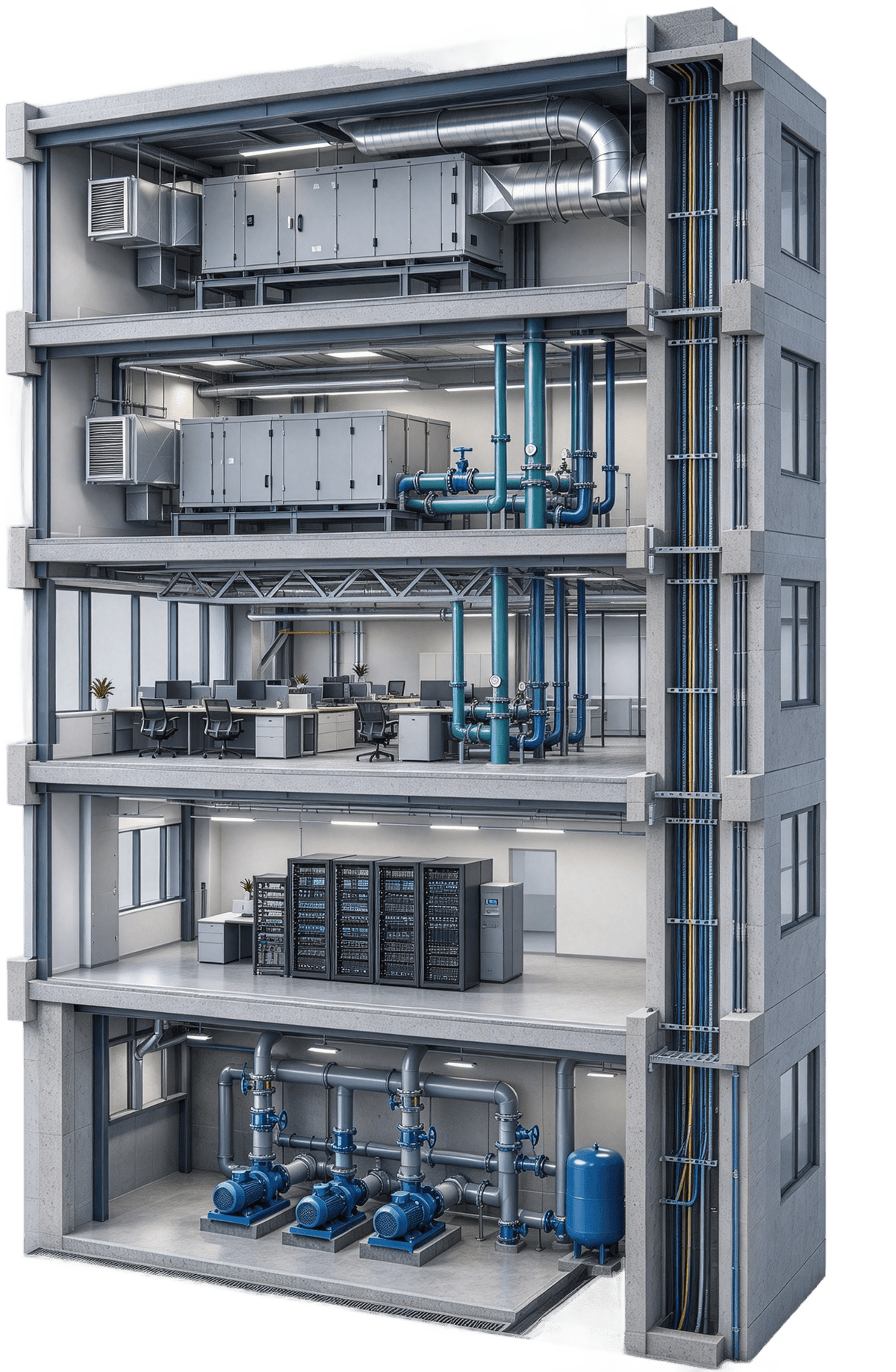
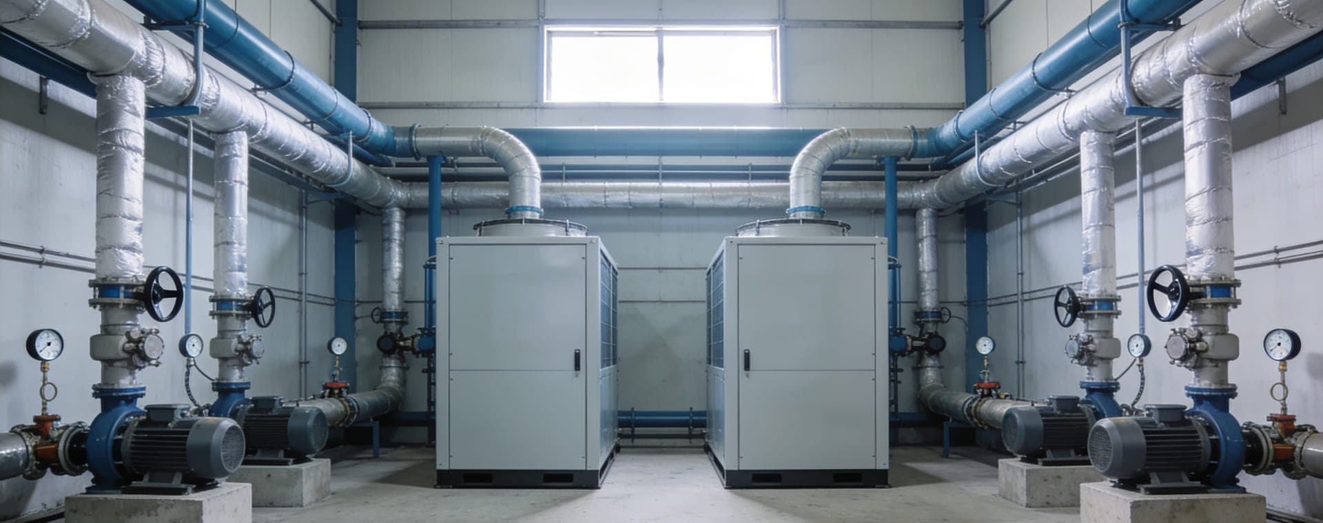
Central HVAC plant room with air handlers monitored by remote I/O
TECHNICAL NOTE

What Is a Remote I/O Module? How DI, DO, AI and AO Signals Map

Remote I/O puts the I/O points in the field and reports back to the controller over a single RS-485 or network cable. Using an air handler as a real-world example, see which signal each sensor and actuator uses, then estimate how many modules you need.

Published
REMOTE I/O

What is remote I/O?

There is one controller, but sensors and actuators are spread across floors and plant rooms. Remote I/O moves the terminals next to the equipment, converts field signals into Modbus data there, and sends them back over a single RS-485 or network cable.

Commercial building cutaway: remote I/O in each plant room connects back to the control room over Ethernet and RS-485
SCADA / BMS host
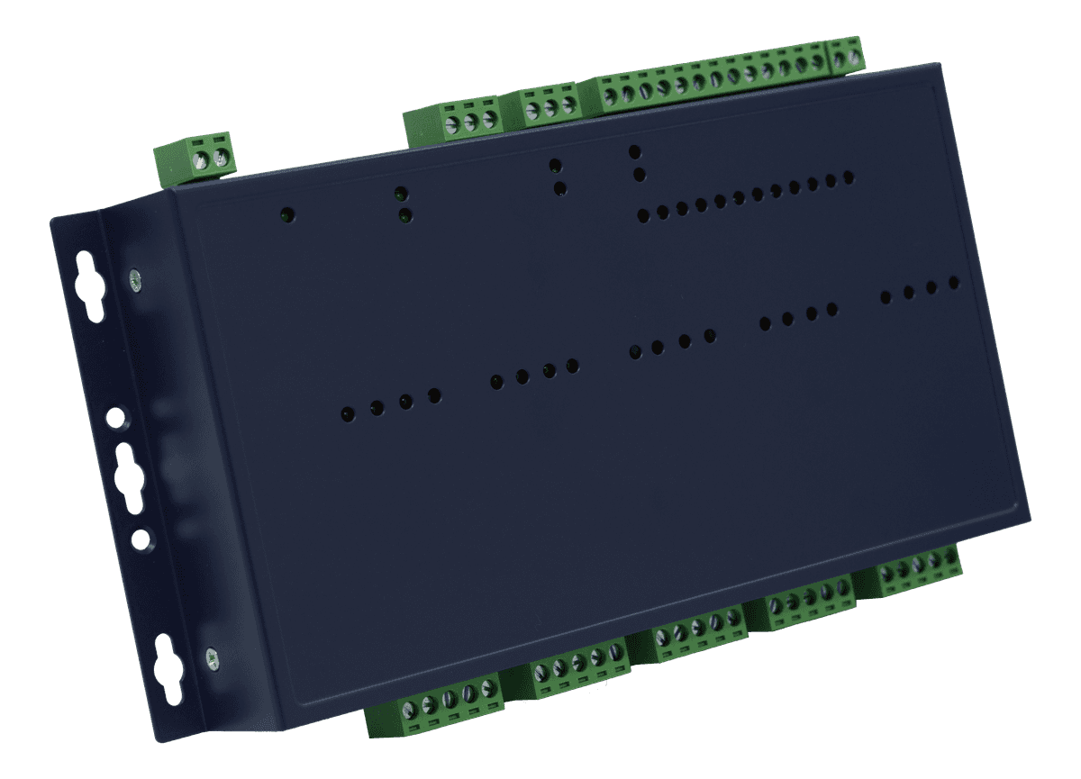
LLD-Modbus32E-01 5F HVAC room
5F HVAC room
LLD-Modbus32E-01
LLD-Modbus32E-01 4F HVAC room
4F HVAC room
LLD-Modbus32E-01
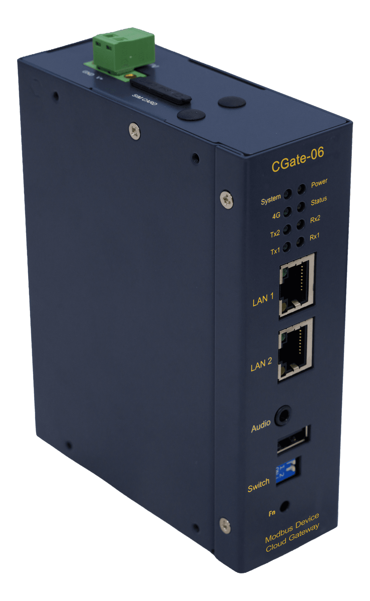
CGate-06 2F control room
2F control room
CGate-06 gateway
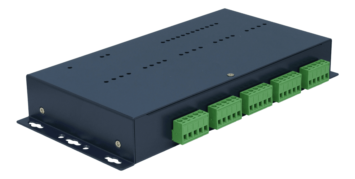
LLD-ModbusIO-01 1F pump room
1F pump room
LLD-ModbusIO-01
Modbus TCP
Modbus TCP
Modbus RTU → TCP
Modbus RTU

How the data travels

Wire locally
Wired to the I/O on the same floor
Modbus TCP
Straight back to SCADA over Ethernet
Modbus RTU
Converted to Modbus TCP by CGate-06
Ethernet
RS-485
Moving dots = data returning to the control room. Layout is an example.
LLD-Modbus32E-01 5F HVAC room
5F HVAC roomLLD-Modbus32E-01Modbus TCP
LLD-Modbus32E-01 4F HVAC room
4F HVAC roomLLD-Modbus32E-01Modbus TCP
CGate-06 2F control room
2F control roomCGate-06 gatewayModbus RTU → TCP
LLD-ModbusIO-01 1F pump room
1F pump roomLLD-ModbusIO-01Modbus RTU

How the data travels

Wire locally Wired to the I/O on the same floor
Modbus TCP Straight back to SCADA over Ethernet
Modbus RTU Converted to Modbus TCP by CGate-06
Ethernet
RS-485
Moving dots = data returning to the control room. Layout is an example.
EXAMPLE · AHU

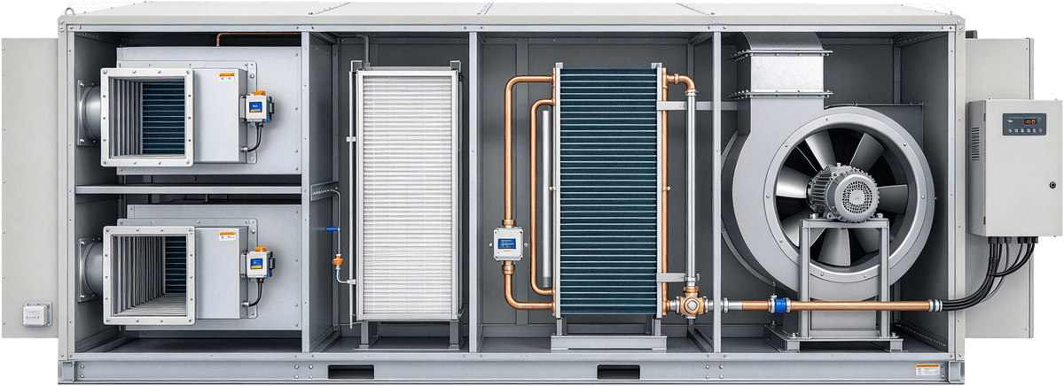
One air handler uses all four signal types

Click a device on the drawing or a card below to see which signal it sends or receives and which module it connects to.

Air handler cutaway: mixing-box dampers, filter, cooling coil with chilled-water valve, supply fan and VFD
DI · In

Filter pressure switch

Trips when the pressure drop across the filter exceeds the setpoint, signaling that the filter needs changing.

Connects toModIO-DI
AI · In

Return-air temperature

Measures room air returning to the unit, typically an NTC or a 4–20 mA transmitter.

Connects toModIO-AI
AI · In

Supply-air temperature

Measures discharge-air temperature; it is the feedback for the chilled-water valve loop.

Connects toModIO-AI
DO · Out

Supply-fan start/stop

Starts and stops the supply fan through an interposing relay or contactor.
Connects toModIO-DOModIO-Relay
AO · Out

Outdoor-air damper

Sends a position command to the damper actuator to set how much outdoor air comes in.
Connects toModIO-AO
AO · Out

Chilled-water valve

Modulates chilled-water flow through the coil to control supply-air temperature.
Connects toModIO-AO
AO · Out

VFD speed

Sends a frequency command to the fan VFD to adjust airflow.

Connects toModIO-AO
SIGNAL TYPES

Four signal types: direction first, then digital or analog

A signal coming from the field into the controller is an input; one going out from the controller is an output. A signal with only two states (on/off) is digital; one that varies continuously is analog.

Matching modules in this series: DI → ModIO-DI, ModIO-12DI; DO → ModIO-DO, ModIO-Relay, ModIO-12DO; AI → ModIO-AI, ModIO-AI+; AO → ModIO-AO, ModIO-AIAO. All fit the module slots of the LLD-ModbusIO and LLD-Modbus32E series.

DIGITAL INPUT

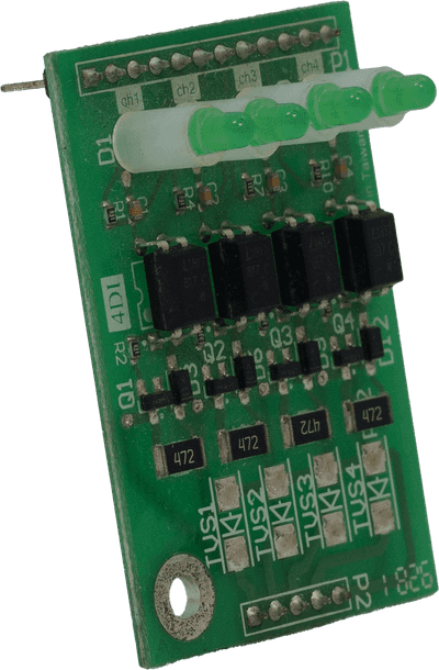
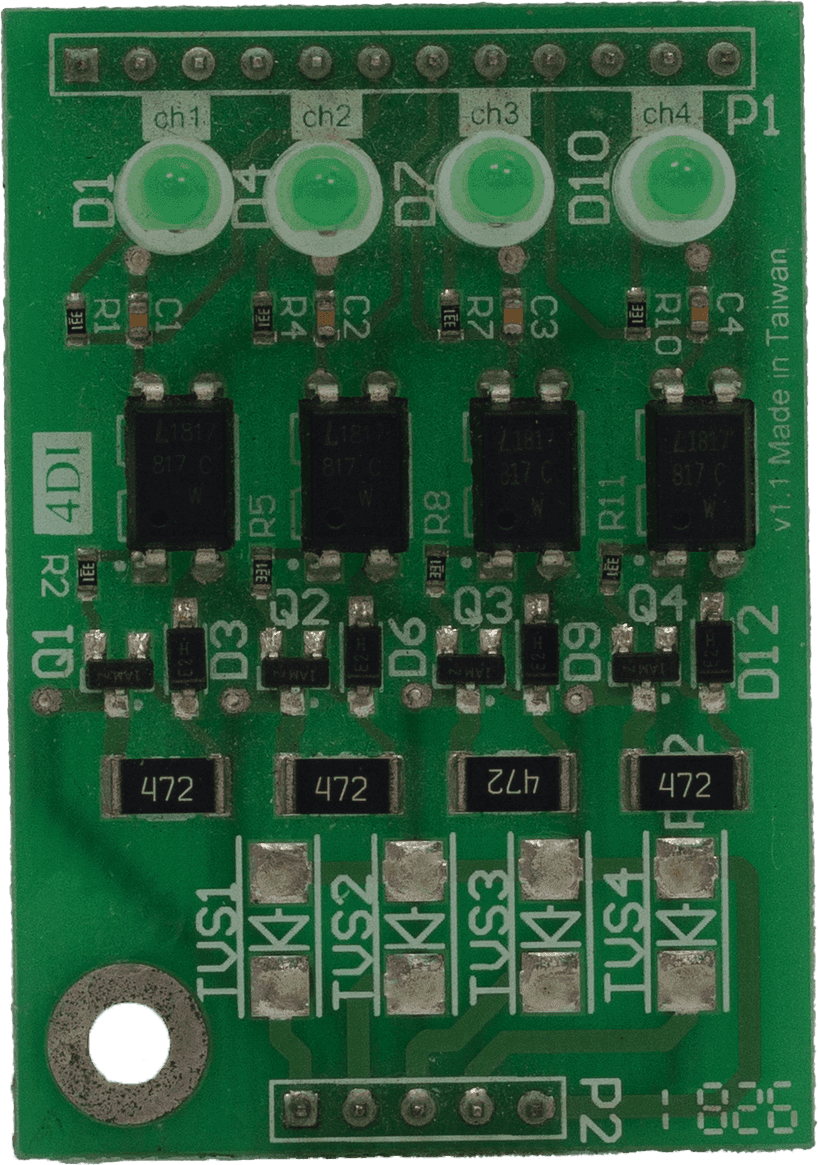
A field contact closes or opens and the module reads it as 1 or 0 — it tells you what state something is in.
Contact type
Wet contact (sink mode); the field side must supply the voltage
Input voltage
5–24VDC
Protection
2000Vrms isolation + 400W surge protection
Recommended sensors
3-wire PNP (sourcing) sensors
Option
ModIO-12DI (fits the EXT expansion slot)
Common uses
  • Run / fault status
  • Door contacts, limit switches
  • Level switches
  • Differential-pressure switches
  • Emergency-stop interlocks
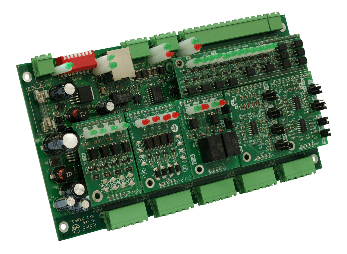
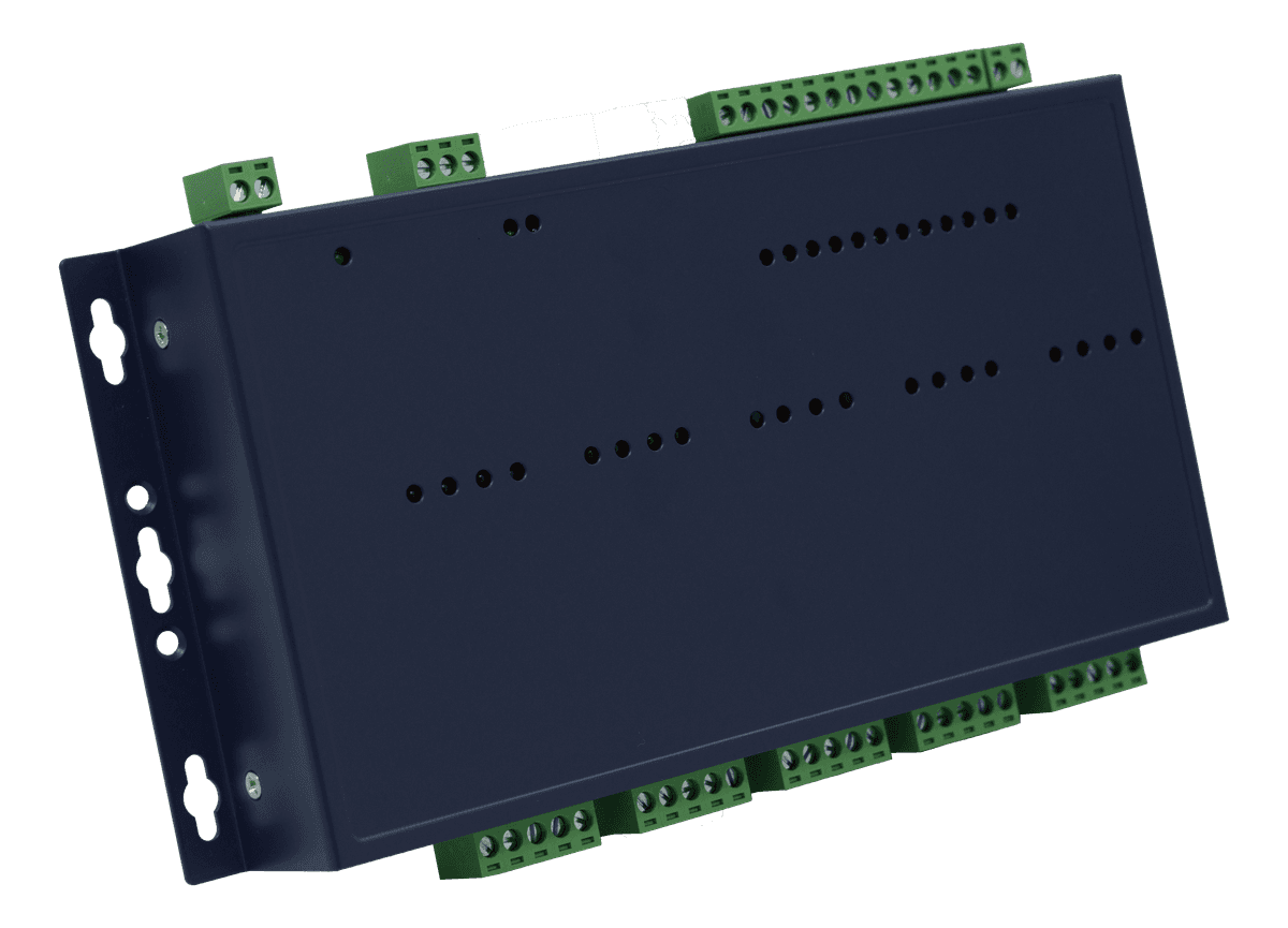
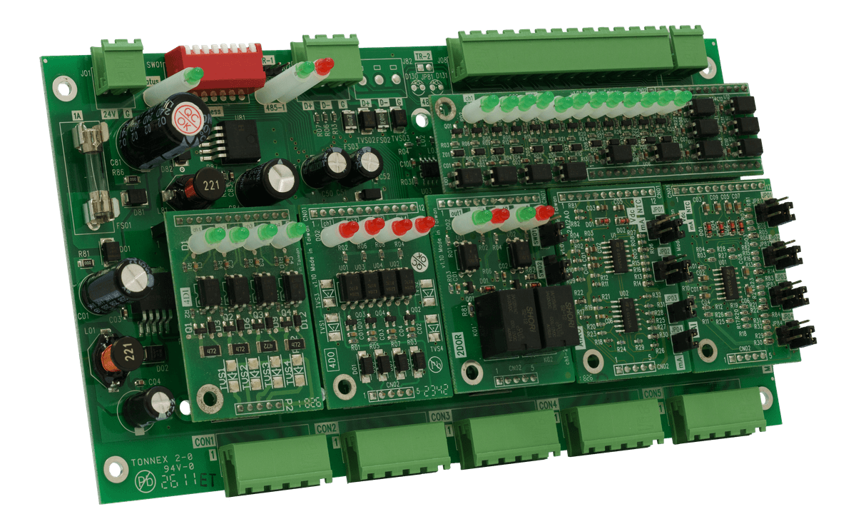
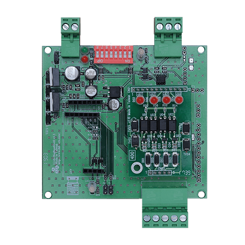
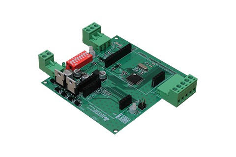
ModIO-DI digital input module, angled view
ModIO-DI digital input module, front view

DIGITAL OUTPUT

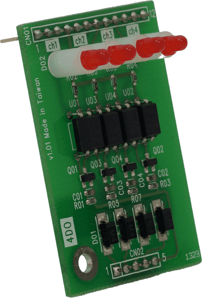
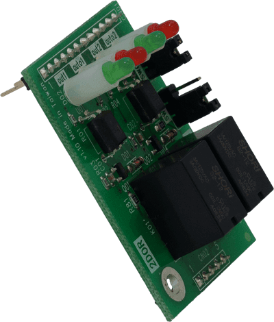
The controller issues a command and the module switches the output on or off. Large loads go through a contactor; small loads can be driven directly.
Common uses
  • Pump / fan start-stop
  • Lighting circuits
  • Beacons, buzzers
  • Solenoid valves
ModIO-DO open-collector output module
ModIO-Relay relay output module
ModIO-DOModIO-Relay
ModIO-DOOpen collector
DODO-COMOptocouplerIsolated drive
  • 5–30VDC@200mA load; DC loads only
  • The field supplies the load power; the load sits between the supply and the DO terminal
  • 2000Vrms isolation + 400W surge protection
  • Option: ModIO-12DO (fits the EXT expansion slot)
ModIO-RelayRelay, SPDT
COMNONCCoil
  • 2A@24VDC / 1A@120VAC contact rating
  • Can switch AC loads; the contact itself carries no voltage
  • Auto / manual control

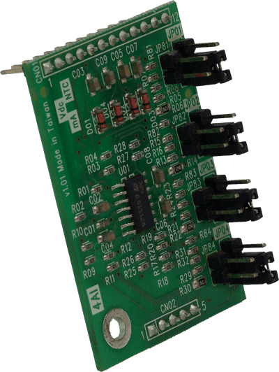
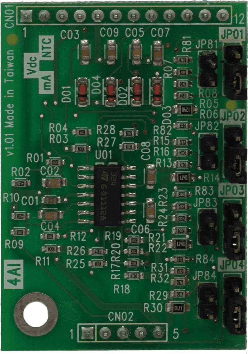
ANALOG INPUT

A sensor turns a physical quantity into current, voltage or resistance and the module measures it — it tells you how much.
Signals
4–20mA / 0–10VDC / NTC signal types
Resolution
ModIO-AI 12-bit; ModIO-AI+ 16-bit high resolution
Signal selection
Set with the on-module jumpers to match the sensor output
Common uses
  • Temperature, humidity
  • Pressure, differential pressure
  • Flow
  • CO2
  • Level
ModIO-AI analog input module, angled view
ModIO-AI analog input module, front view

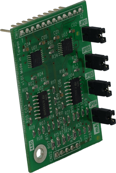
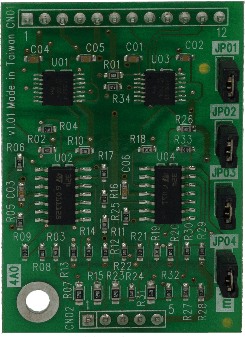
ANALOG OUTPUT

The controller computes a proportion and the module outputs the matching voltage or current — it sets how far something opens.
Signals
0–20mA / 0–10VDC
Resolution
12-bit
Note
Check whether the device takes voltage or current before setting the output type
Low point count
ModIO-AIAO (2 AI + 2 AO)
Common uses
  • Proportional valves
  • Damper position
  • VFD speed command
  • Dimming
ModIO-AO analog output module, angled view
ModIO-AO analog output module, front view

POINT COUNT

Estimate your point count

Enter the point counts from your I/O list to see the modules and base units you need.

  1. 1
    Points
  2. 2
    Uplink
  3. 3
    Modules
  4. 4
    Contact

STEP 01 / 04

Enter your point counts

Sort each point on your I/O list into the five types below and enter the counts. Split DO by load: open collector for small DC loads, relay for AC or loads that need isolation.

DIGITAL
Input
Open Collector
Relay
ANALOG
Input
Output

STEP 02 / 04

Choose the uplink

How the remote I/O reports back to the controller or SCADA decides which base unit you need.

STEP 03 / 04

The modules you need

No points entered yet — go back to step 1 and fill them in.

This estimate leaves out the optional EXT slot (ModIO-12DI / 12DO) and ModIO-AIAO; confirm the final configuration with the configurator and our sales team.

STEP 04 / 04

Send us your requirements

Your point counts and uplink are filled into the email automatically; we will check the configuration and reply with a recommendation.

Points: —; Uplink: RS-485 (Modbus RTU)
FAQ

FAQ

Should the DI module be paired with NPN or PNP sensors?

The DI modules in this series are sinking inputs, so pair them with 3-wire PNP (sourcing) sensors.

4–20 mA or 0–10 V — which should I use?

The sensor decides, not the module: if the sensor outputs 4–20 mA, set the input to 4–20 mA; if it outputs 0–10 V, set 0–10 V. ModIO-AI is switched with on-module jumpers. If the sensor offers both, 4–20 mA holds up better over long runs and in noisy environments.

What kind of signal does the DI module take?

The DI modules in this series take wet-contact inputs: the field provides the 5–24 VDC loop supply and the module does not power the contact, so a dry contact cannot connect directly. PNP (sourcing) sensors are recommended.

How does remote I/O differ from a DDC controller?

Remote I/O only carries signals and leaves the logic to the controller; a DDC runs its own control program. This series supports LLD-DDC, so control logic can run on the base unit itself.